 |
The following article is a component of the August 1998 (vol. 50, no. 8) JOM and is presented as JOM-e. Such articles appear exclusively on the web and do not have print equivalents.
|
Computer Modeling: Overview
The Three-Dimensional Simulation of Flow Pattern in Equal-Channel Angular Extrusion
H.J. Cui, R.E. Goforth, and K.T. Hartwig
 |
|---|
| CONTENTS |
|---|
|
Equal-channel angular extrusion is an innovative forming process to extrude material without substantial change in its geometric shape. Multiple extrusions from equal-channel angular extrusion allows heavy plastic strain to the bulk material. More importantly, by changing the orientation of the billet between successive extrusions, sophisticated microstructures and textures can be developed in the material. According to the orientation chosen after each pass, four fundamental equal-channel angular extrusion routes (A, B, C, and C´) are defined and used for different purposes. It is important to understand the flow pattern after each route because it significantly impacts the formation and orientation of the microstructures. this article, we establish a three-dimensional computational model to predict the flow pattern. To this end, a unified mathematical description for all equal-channel angular extrusion routes will first be given. After that, we construct the self-consistent velocity field for equal-channel angular extrusion. Based on the results from numerical calculation, the flow pattern can be graphically simulated for any route and pass number.
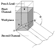
Equal-channel angular extrusion (ECAE) is an innovative forming process to extrude material bar or billet without substantial change in cross section.1 The mechanism of ECAE is illustrated in Figure 1. The die system of ECAE consists of two channels with identical rectangular cross sections connected through the intersection (AA´BB´) by an adjustable angle  . For extrusion, the material billet is placed in the first channel and then extruded out from the second channel by applying a punch load. It has been demonstrated that, after extrusion, the entire billet (except a small part at the ends) is plastically deformed in nearly the same way
 by simple shear.
 |
 |
| Figure 1. A schematic of ECAE. |
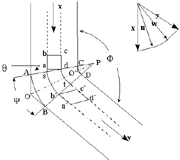
Figure 2. (a) The fan deformation pattern of ECAE and (b) a velocity-vector diagram. |
ECAE has many noticeable technological benefits.2 Since the cross section of the billet remains nearly unchanged after each extrusion, this process is repeatable, and, hence, heavy plastic strain can be obtained by multiple extrusions. More importantly, if the cross sections of the channels are designed as square, the orientation of the shear plane can be easily changed by rotating the billet (± n 90°, n = 1 or 2) for subsequent extrusions. This simple fact makes it possible to use different routes (A, B, C, and C´), which are defined based on the different combinations of the shear planes, to develop different microstructures and textures within the bulk material.
It is expected that material properties can be estimated after extrusion. An efficient way to do this is to study the formation and orientation of the microstructures, which can be characterized by the flow patterns.
| THE MATHEMATICS OF ECAE |
|---|
 |
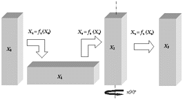
| Figure A. A typical cycle of ECAE. |
Figure A shows a typical cycle of the ECAE deformation process. X0, X1, X2, and X3 represent billet positions in a global coordinate system at different stages during the forming process r. The cycle can be decomposed into three sub-processes. In the first subprocess,
f1: X0
 X1 X1
the billet is extruded from the original position X0 to the completely deformed state X1. In the second subprocess,
f2: X1
 X2 X2
the billet at X1 is reoriented vertically to X2. In the third subprocess,
f3: X2
 X3 X3
the billet at X2 is rotated about its long axis through a certain angle (n90°) to a new position X3, which is ready for the next extrusion cycle.
Based on the rotated angle chosen in the third subprocess, the four different routes can be defined as follows: A route, n = 0; B route, n = +1 at even pass, n = -1 at odd pass; C route, n = 2; C' route, n = 1.
Following the mathematical meanings of f1 ( ), f2 ( ), and f3 ( ), the following relation exists
|
X3 = f3 (X2) = f3 (f2 (X2) ) = f3 (f2 (f1 (X0))) = f (X0) |
(A)
|
This means that if the forms of f1 ( ), f2 ( ), and f3 ( ) are determined, the one-to-one mapping of f ( ) between the material particle in an original position (X0) and its position after one ECAE cycle (represented by X3) can be established. In other words, the movement of any material particle can be traced. The transformations f2 ( ) and f3 ( ) represent combinations of pure rigid-body translation and rotation and are easy to determined.
The deformation process represented by f1 ( ) is associated with a two-dimensional shear deformation. Unfortunately, the analytical form of f1 ( ) does not exist, and the relationship X0  X1 has to be numerically calculated. X1 has to be numerically calculated.
Suppose that Xt is an intermediate configuration of the billet between X0 and X1 at moment t, then the next configuration, Xt+ t, after time increment t, after time increment  t can be determined by t can be determined by
Xt+ t = Xt + t = Xt +  U = Xt + V(Xt) U = Xt + V(Xt) t t |
(B) |
The velocity of the material particle [V(Xt)] is derived from the ECAE self-consistent velocity field.
|
To determine the material-particle velocity in terms of different regions, a fan-like deformation area (PAB in Figure 2) is assumed for ECAE. Beyond the fan area, the material particle is assumed to experience pure rigid-body movements with velocity x or y, depending on its position. When the material particle passes through the shear line AC or BD, its velocity direction will abruptly change either from x to u or from w to y.
As the velocity-vector diagram in Figure 2 indicates, the velocity of the material particle within the fan area will vary its direction continuously and keep the same magnitude (i.e., |u| =|w|). The relationships between the magnitude of x and u, x, and y can be derived from the constant volume constraint
|x| sin |AC| = |u| |AC|=|y| sin
 |BD|
|BD|
in which
See Figure 2 for definitions of  ,
,  , and
, and  . Therefore, |u| = |x| sin
 and |y| = |x|.
With the above velocity field, it is possible to conduct numerical calculations using Equation B to keep track of the movement of material particles. To predict the deformation pattern based on the numerical results, a visualization program is developed.
 |
 |
 |
| Figure 3. A cross section of the material billet. |
Figure 4a. The flow pattern after four passes following route A |
Figure 4b. The flow pattern after four passes following route B |
 |
 |
 |
| Figure 5. Illustration of the surface effect after the (a) first, (b) second, and (c) fourth passes following route B. |
Figure 3 shows a cross section of the material billet 15 cm long and 2.5 cm in both width and thickness. Figure 4 gives the outputs of the visualization program for its deformed geometry after four passes following route A and route B, respectively, through a 90° extrusion angle ( ) and a zero-degree fan angle (
 ). The fact that the original plane has only been elongated along the flow direction (Figure 4a) shows that route A can be used to develop lamellar microstructures. On the other hand, for route B (Figure 4b), the original cross section has been twisted and extended along the extrusion axis. This means that route B can be used to develop a distorted fibrous structure.
The visualization program also helps illustrate surface effects (Figure 5). The original geometry of the billet is represented by 60 x 10 x 10 small cubic elements. Figure 5 shows the results for first, second, and fourth passes following route B with
  = 90° and
  = 0°. Clearly, except for the first pass, route B does not provide a uniform deformation pattern, but rather nonuniform surface and end effects.
A unified mathematical description has been established for ECAE extrusion. With the assumption of a fan-like deformation pattern, it is possible to derive the self-consistent velocity field for ECAE. Based on the results from numerical calculations, a visualization program was developed that can graphically simulate the flow pattern for any route and number of passes. The results of the visualization program allows the examination of the deformation pattern for any region with a billet as well as the surface and end effects. The use of the simulation method is helpful in the development of an understanding of ECAE deformation effects, including the formation of different microstructures and material properties.
1. V.M. Segal et al., "Plastic Working of Metals by Simple Shear," Russ. Metall. (English translation), 1 (1981), pp. 99-105.
2. V.M. Segal, "Material Processing by Simple Shear," Mater. Sci. Eng., A197 (1995), pp. 157-164.
ABOUT THE AUTHORS
H.J. Cui, R.E. Goforth, and K.T. Hartwig are currently at the Department of Mechanical Engineering at Texas A&M University, College Station, Texas.
For more information, contact R.G. Goforth, Texas A&M University, Materials Science and Engineering, College Station, Texas 77843; (409) 845-3645; fax (409) 862-2418; e-mail rgoforth@mengr.tamu.edu.
Copyright held by The Minerals, Metals & Materials Society, 1998
Direct questions about this or any other JOM page to jom@tms.org.


 . For extrusion, the material billet is placed in the first channel and then extruded out from the second channel by applying a punch load. It has been demonstrated that, after extrusion, the entire billet (except a small part at the ends) is plastically deformed in nearly the same way
 by simple shear.


 X1
X1 X2
X2 X3
X3 |AC| = |u| |AC|=|y| sin
 |BD|
|BD|
 ,
,  , and
, and  . Therefore, |u| = |x| sin
 and |y| = |x|.
 ) and a zero-degree fan angle (
 ). The fact that the original plane has only been elongated along the flow direction (Figure 4a) shows that route A can be used to develop lamellar microstructures. On the other hand, for route B (Figure 4b), the original cross section has been twisted and extended along the extrusion axis. This means that route B can be used to develop a distorted fibrous structure.
The visualization program also helps illustrate surface effects (Figure 5). The original geometry of the billet is represented by 60 x 10 x 10 small cubic elements. Figure 5 shows the results for first, second, and fourth passes following route B with
  = 90° and
  = 0°. Clearly, except for the first pass, route B does not provide a uniform deformation pattern, but rather nonuniform surface and end effects.